How to enable RRCP
How to enable RRCP support.
Abstract
This HOW-TO describes method of enabling RRCP protocol on switches, that contains RRCP-capable switch controller (i.e. RTL8316B, RTL8318P, RTL8324, RTL8326 or RTL8326S), but RRCP protocol does not work out-of-the-box.
Method 1: EEPROM adding
Some switches comes with an empty place in PCB, ready for EEPROM chip to be soldered in. This method is preferred for such switches.
-
First, open your switch and take a look at PCB. Find a place for EEPROM and figure out it’s type - SOIC8 or DIP8.
-
Get a 24C02 or higher (24C04, 24C08…) EEPROM chip itself in approriate package (SOIC8 or DIP8).
-
Program it with appropriate data using I2C programmer (PonyProg or even bunch-of-wires-lpt-dongle will do), using ready EEPROM configuration image
-
Solder it in place.
Method 2: Fixing MAC-address for RRCP-enabled switches
Some switches (like D-Link DES-1024D and Compex SXP1224B) already have EEPROM soldered and RRCP enabled, but contains
original Realtek crap (52:54:4С:01:02:03) instead of normal MAC-adrress, so using such devices in production is
impossible (you can have no more than one device in L2-segment). The original solution was to desolder EEPROM chip,
program it with appropriate data and solder it back (like in method 1). But there is much simpler solution: EEPROM
write-enabling
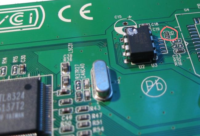
Pin 7 (“WP”) of 24C02 EEPROM chip is responsible for write-protecting it. Chip can be writhen, if this pin is logic-low (voltage is near GND level). If pin 7 is logic-high (voltage near VCC level), chip is write-protected. I.e. D-Link DES-1024D’s 24C02 has this pin in logic-high level due to R5 resistor tieing it to VCC (see picture):

Note, that Pin 7 contains no internal pull-up inside chip, thus, when pin is floating it reads low level. So, to write-enable EEPROM chip, we need to solder off R5 resistor. You may even simply (carefully!) destroy R5, if can’t desolder small parts.
Method 3: Pin strapping
This method is for switches, containing no place for EEPROM chip. RTL83xx chips supports one more method of configuring (pin-strapping). To use this method, you need to solder in resistor (470 Ohm to 10kOhm) between appropriate pin(s) and ground (power) plane (details is chip-dependent).
Note, that this method implies a 2 serious limitations:
1) Switch will have no MAC address (it will have 00:00:00:00:00:00 as MAC address to be exact) - and as you guess, you
can’t have more than one such switch in a network. Moreover, some “smart” switches (at least, 3COM’s 3c1100/3c3300)
tend to filter out ethernet frames with 00:00:00:00:00:00 as destination MAC address, and you will never reach your
RRCP-enabled-by-pinstrap switch if such “smart” switch is in the middle.
2) No configuration is saved permanently - you need to constantly (maybe one time per minute - from crontab) reconfigure such switch in order to survive switch reboot seamlessly.
RTL8316B
Pin 121(EnRRCP) is used in RTL8316B to preconfigure RRCP protocol enabled. You need to pull-up this pin to enable RRCP (i.e. solder in resistor between pin 121 and power-plane - VCC). Nearest pins, connected to VCC are 114 and 128. Note, that Pin 121 is also used as output for port 5, so do not try to connect it to VCC directly - you will burn port 5.
RTL8326/RTL8326S
Pin 35(DisRRCP) is used in RTL8326/RTL8326S to preconfigure RRCP protocol enabled. You need to pull-down this pin to enable RRCP (i.e. solder in resisior between pin 35 and ground-plane - GND). Nearest pin, connected to GND is 34. Note, that Pin 35 is also used as output for port 10, so do not try to connect it to GND directly - you will burn port 10.